I made the Grid Lines green in order to differentiate them from the blue Topology Lines and the red Quads. The task was tedious and awkward at times, but within 3DS Max is a Snaps Toggle that allows you to join the lines you draw to the vertices/corners and edges of another, making my job a little bit easier.
It got difficult at times because of the way some of my Quads had been drawn. Because of this, I had to add some extra Grid lines for some areas, while for others I actually had to simplify and not draw as many. Lines were not drawn for the eyes, nostrils or lips, because those are to be modeled later.
After the grid lines were drawn, one of the quads had to be converted into an Editable Poly:

It would sound easier and less time consuming if I simply converted all of them at the same time, but according to the tutorial, what needed to be done instead was to attach this one shape to the rest of them using the Modify Panel. After selecting all the lines in the dialogue box that appeared, all of the quads were merged together to create one shape:

I had to undo this process a couple of times because I noticed one or two gaps in the shape, where some of the lines hadn't been connected properly. After deleting and redrawing these lines to fill the gaps that were previously left, the Attach modifier was used to convert them into a group of editable polys: however, the shapes were all still seperate, so what I had to do next was use the Weld modifier to essentially link the shapes all together as one. The shape has the grid lines all over it because I took this screengrab with the viewport set to show any edged faces.
As I'm about to move onto the next step in the modelling process, I'll be working with the inane fear that I've probably done at least one thing wrong. For this reason, I have saved a copy of the file so that I can make any neccesary changes to the grid lines.
For the next stage, I needed to align all of the vertices at the middle of my face, and I did that by clicking on an 'X' button under the editable poly's Edit Geometry tab:

Now that the vertices were all aligned, I needed to go into the left viewport, and click and drag the ones that I had previously selected out. After making a minor adjustment to my left reference plate, I then dragged each of the vertices along the X axis to align them with my facial features as best as possible, as shown in the screengrab below:

So now what I basically need to do is keep dragging the vertices to match up with the facial features (though as the above screengrab shows, it's be difficult to do that because the photo is being hidden by the shape. To solve this problem, with the shape selected, you can press Alt+X to make it semi-transparent, so that you can see through it, making matching the facial features much easier).
This bit will be finished before my next entry, but before I finish tonight, I've got a tip to provide.
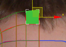
Now if your Gridlines have been drawn in a similar way to my own (some lines connecting to the edges of a quad instead of a vertex), you may notice that when you need to drag one of these particular vertices out, it will create an unneccesary gap in the object that you do not want:

This happens because the vertex that has been dragged out is not connected to the edge of the other quad, because there is no vertex there for it to weld to.
By this stage you will most likely be dragging your palm down your face, with the knowledge that after all that time you've spent working on it, an error like this occurs and you have to start all over again... but fear not, for I have a solution to solve this problem very quickly!
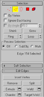
Basically, what you need to do is go to the Edges selection under Editable Poly, and under there you should see a button labelled "Add Vertex". The screengrab below will show you what you need:

Now we need to go into the Front viewport and zoom into the gap. This will make inserting the new vertex easier:

Once the new vertex has been added, click on the Target Weld button, and then click and drag from one of the two vertices to the other...

Problem solved! This technique may also be of use if you feel that you need to to add vertices to create more quads if you need them at all.
No comments:
Post a Comment