Friday 30 October 2009

Group Project Part 1 - First Meeting

Just days before handing in that dreaded 3D head, my group made up of only three people at the time had our first "official" meeting. We basically looked through the photos that were taken by one of my group members at the museum, and we decided on a machine known only as "Arthur Mumford's Favourite Boiler Feed Pump". No official name, model number or anything like that, all we know that it was apparently Mr Mumford's favourite.


Since I couldn't go to the museum myself, I wasn't able to get too much of a good look at the machine, so it's just as well that Craig took plenty of photos from different angles for me to use as reference images for my part of the machine.

Craig's task as far as modelling goes is to make the left part of the machine, and he will also be gathering any information he can get regarding this machine. He also seems to have something of a leadership role within the group. Ryan will be modelling the right side, and he hopes to be able to work with elements such as fire and water. And finally, since these two have given me good feedback for my animations from last year, I have been given the task of modelling the piece in the middle, the only part which actually needs animating.

I'll go into a bit more detail in my next entry, which will basically be a copy of what I've posted in the group blog.

Thursday 22 October 2009

Week 5c - My Thoughts


So what did I think of this assignment overall? For my first time handling "organic" 3D modelling, it wasn't too bad, but it certainly wasn't easy. After the simpler techniques I learnt last year, something as complex as a somewhat realistic version of my own head was quite a huge leap to take, especially considering the fact that I had only five weeks to complete it (technically, you could say it was actually only four weeks, since we only found out about the assignment at the end of the first week back).

I'm quite pleased with the result, but as I mentioned in my previous blog entry, it's not perfect, and if I had just a little bit more time to finish it off, the end result would definetely have been of better quality. Of all the various parts of the head that were modelled, I'd say that the ears were definetely the most difficult part. They look OK anyway, but because I did so many different things ti the inside of the ear, it is in actuality a bit of a mess. As far as tutorials go, I was only able to make it as far as applying the material to the 3D model, so I wasn't able to do more to it like applying bump maps, or even give my 3D self some hair.

Speaking of the tutorials, I found them slightly difficult to follow: Mr Maslowski had a habit of skipping ahead on parts that I may have needed help with, although to be fair this allowed me to do my own thing and see if I could do it myself - which wasn't always a good thing. He also skipped the eyelids (and as a result, my 3D model has none) and the eyeballs (which I made myself anyway) and I don't think he showed us the neck creation very clearly, if at all (I still managed to pull if off myself, so it doesn't matter too much).

If I was given another chance to try this again, I think I would turn it down straightaway probably be able to do it with a bit more ease, and could probably do the earlier parts of the modelling process without the tutorial's help.


Here's a 360 dregree view of my 3D head:

Week 5b - Finishing Touches

In my last entry, I covered the development of perhaps the most complicated task - at least, as far as modelling goes - for this whole project: the ear. I've finished attaching it to the ear (and once again, the symmetry modifier saves me the trouble of modelling the other one, yay!), and here's how the head looks thus far:


Another thing I pointed out in my last entry was how difficult it was to attach the ears to the head, purely because of the difficulty I had getting the camera in place. So what I had to do was drag the ear outwards so that I could get a better look at where the vertices would all be attached.

Once that was done, I welded the ear to the head, and then carefully selected all of the ear's vertices to be pushed back into place. For some reason, this caused some of the ear's polygons to go inside the head, and I can't go in and save them without ruining the appearance of the head which I already feel looks OK anyway. As Jo taught us last year during 3D Modelling and Animation: If you can't see it, it doesn't matter. So I left the polygons alone.

Now, the only thing left to be done is to make my 3D alter ego look more human and less like a Namek... and this will be done by adding a material! According to the tutorial, the first step is to temporarily turn off all modifiers, go into editable poly and apply a modifier called Unwrap UVW. I then had to select the Face option underneath that modifier, and use Paint Selection Region to go over everything except for the ear, which has to be done seperately.


After rotating the camera to make sure that everything is selected, the next step was to scroll down under Map Parameters and select the Cylindrical button. After adjusting the position of the cylinder thing, I then had to apply a Checkerbox material to the head:


It doesn't look quite right, partially because Mr Maslowski made the addition of his checkerboard pattern look easy. Where he got the whole thing, I only got 4 squares, so I had to increase the amount myself. Also notice how, for some reason, there are hundreds more on the ear.

Now he's instructed me to click on Edit underneath Parameters, which brings up this window:


Now I'm slightly confused, because in his video, we can clearly see that his ear is also there. I for some reason can't see mine - hold on, what's that green line going across the top right corner? I'm going to zoom out so we can find out what it is...


AH! There it is, only it's been made gigantic for no reason. Now I need to scale the stupid thing back down...


There, that's better. But I'm going to leave it aside for a moment, as instructed, because it's currently not important (on a side note, this has fixed the problem I had before where the ear had hundreds more checkers on it than the head).

From here, I now need to start adjusting things which I'm not going to go into much more detail about because the tutorial already does that.

A few hours later, after much frustration, confusion and hair pulling over trying to follow the tutorial, I have at last come to this point, where I now have a UV layout:


After some adjustments, this UV map has been rendered and saved as an image that will be used in Photoshop.


In Photoshop I've been copying bits of my photos and pasting them above the gridlines in the above snapshot. Because the edges of these cutouts are blatantly obvious, with my skin being darker in one place than another thanks to that pesky thing we call shading, I've had to use both the smudge and dodge tools in an attempt to clean it up, while ironically making even more of a mess of it:


I have to admit that it could be much worse than that, and as I'm quickly running out of time, I have no choice but to overlook this and move on (and I only discovered via the tutorial, way too late, that I could have used the clone tool instead, which would have been even better. Thanks for nothing!).

For some bizarre reason, once I imported the file into 3DS Max, while part of the forehead looks absolutely fine, the rest... well, just look at this screengrab. I'm speechless as to how stupid computer programs can be sometimes:


I'd love to know what the heck happened here. As you can see, all but a bit of the forehead came out completely screwed up, with completely random TV static pixels and a trippy liquid-like effect on part of the forehead, despite the fact that it looked nothing like this in Photoshop, and the fact that this was the format I was instructed to import it in.

I couldn't give up here, especially not after coming this far. So I had to go for a Plan B, that is, to import it as a different file format instead. Rather than a Photoshop PSD like before, I now imported it as a PNG file, and that instantly fixed my problem:


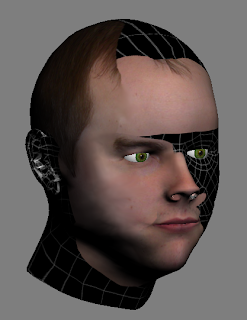
And I have to say that it's not looking bad at all. Now it's time to start making those final adjustments...


And at long last, it is finished. But sadly, it's not perfect, and now that I've basically run out of time, there's really not much more I can do to it. I'm disappointed that I had to resort to the smudge and dodge tools for some parts of the face and hair, but it seems to have worked fairly well anyway.

One strange fault I came across was an area up the nostrils which for some reason turned out how it did in the below screengrab, with no apparent way for me to fix it:


Sadly, I don't have enough time to fix this problem, since I can't locate where exactly it's getting the colour from, so I have no choice but to leave it alone.

In my next entry - and my final for this project - I'll post my thoughts, as well as a video showing a 360 rotation of the head to give a better idea as to how the whole thing looks.

Tuesday 20 October 2009

Week 5a - The Dreaded Ears

Now it's time to work on the final part of the head before I add any textures to it: the ears. This is potentially going to be very complex, perhaps even more so than the face, but since this has to be finished and handed in by Friday, it's time to dive in.

I started by adding topology lines and quads on the profile photo, just like I did with my face not too long ago:


I have a feeling that I may have done something wrong, but I didn't have enough time to worry about this as I shortly moved onto the modelling process:


Once again, this was modelled in a very similar way to the face: the quads were drawn as gridlines on 3DS Max, and joined together by the vertices. Much like when modelling the face before, I needed to simplify the quads in some places, while adding more in others, however the general shape of the ear's detail can still be seen.

After positioning the vertices to define the overall shape of the ear, it now looks like this:


It's not exactly perfect, and since I wasn't feeling too well last night, I decided to leave it for the time being and carry on with it today while I can concentrate better. The ear seems as though it's difficult to model, which is because I have only been moving the vertices around, which isn't working properly. Instead, I need to extrude some parts inwards to form the ear canal, much like I did with the nose earlier on (bear in mind that I'm not currently following the tutorial, although I did skip through some of it to see how he was doing it).

In order to help me in modelling the ear, I actually went into Photoshop and turned off the Topology and Quad layers, so that I could see the photo more clearly. After adjusting more vertices and extruding some faces, it now looks more like this...


...a horrible, blocky mess. However, it does look more like an ear - and more importantly, my own ear - than it did before. It looks much better once Turbosmoothed:


This is the closest to a perfect match with my real ear that I've been able to get, but I'm pleased with it anyway. The ear as a whole still isn't finished yet, but apparently the next stage of the tutorial is to attach it to the back of the head.

In order to do so, some of the faces on the side of the head had to be deleted to make way for the ear:


But there's still no detail behind the ear: it needs some thickness of its own. So now what I'm being instructed is to press Alt+Q to go into a 3DS Max function called Isolation mode. From here, all of the edges of the outside of ear were selected by selecting one and then clicking on the loop button.

After doing that, I pressed shift while dragging the edges along the X Axis to create copies of those edges:


As shown by the above screengrab, this has now given the ear some depth and is defining the outer edge. From here I had to continue adding faces to the back of the ear in order to create the back, and make it easier to connect it to the side of the head:


Now I can exit Isolation mode, and start attaching the ear to the head.


At the moment, I'm finding this to be the most frustrating task so far, purely because it is difficult to see where everything needs to go, even when I move the camera in place. Tune in to my next entry to hopefully see the finished head!

Friday 16 October 2009

Week 4d - Head and neck

Well, as far as blogging goes this has been quite a busy week. But at the same time, my 3D head is coming along nicely, and I just finished both the back of the head, and at the same time the neck.


Compared to other students' work that I have seen, there isn't really much of a neck, which is mainly because on my reference photos, my t-shirt is covering up the majority of my neck and shoulder area, so there wasn't really much for me to model.

As far as the sides of the head and the neck go, I did that by myself without following the tutorial, partly because the guy who made it skips ahead without bothering to go through that process, but also because I wanted to try and do this part my own way. I'm pleased with the result, but one part I had trouble with was the side of the neck. While matching it with my reference photo, it for some reason became a bit sharp and pointy:


I think this is more to do with the surrounding vertices, but perhaps when this is Turbosmoothed it will look better. Speaking of which, it's time to see how it looks so far, but first I need to attach the two objects together, using the Attach button under Editable Poly.

Now that the two objects are attached, let's Turbosmooth it to see how it looks!


Hmm... oh dear. That's not how we wanted it to look. On an upside, clicking on Symmetry again automatically creates a copy of the back of the head without me needing to adjust any settings to put it in the right place, but now there's a line going around the side of the head and around to the back, clearly defining the two seperate objects.

There is of course, a cause and solution to this problem: looking back at when I was starting to model the face, while the two objects are attached and treated by 3DS Max as a single object, they haven't been welded together yet. So what has to be done now is to undo Turbosmooth, select all the vertices that should be connected, and click on Weld to finally connect them together. Having done that, we'll Turbosmooth it again and...


Much better. Before I get started on the ears, one more thing I need to adjust is my head shape. Let's face it, nobody's head is really as perfectly round and smooth as that, which I noticed after seeing my own profile view for the first time. Using soft selection while moving the vertices around, I started repositiong them so that they would match the shape of my head. Here's how it currently looks:


Before I add any materials to finish my head off, one more important feature that needs to be modeled is the ear...

Thursday 15 October 2009

Week 4c - Eyes and the back of the head

After finishing the nostrils and lips earlier this week, the next stage in the tutorial was to start working on the back of the head. I then opened the next tutorial video up, only to notice that the guy's already done his eyeballs... wait, what? You're not going to show me how you made them? That's not fair!

So I had to go out of my way to make them myself, without the help of this tutorial. What I did first of all was create a sphere for one eyeball, and then begin working on a material that would make my eyes look somewhat realistic. I had no idea how I would actually do this, so a bit of tutorial hunting on the Internet led me to this useful guide on how to make a realistic eye texture in Photoshop, which allowed me to make this material:


I made the eye brown in the middle and dark green everywhere else to match my own eye colour. The pattern on the eye does look a bit weird when you first look at it, but once I applied this material to the sphere, it actually looked quite good. Bear in mind that the picture above is zoomed into the middle of a large 1000x1000 pixel sized bitmap, because anything smaller I tried did not cover the whole sphere.

After adjusting the position of the eyeball texture onto the sphere, and reshaping the eyesocket area on my 3D face, it now looks something like this:


This is what the whole thing looks like so far, with Turbosmooth on. It was vital that I undid the process straight after taking this screengrab, so that I can carry on with my work.

The eyes look OK for now, but I think the colour might be a bit too bright (if you look at my photos in earlier entries, you'll notice that my eyes are quite dark in colour). If I'm not happy with it by the time I'm finished with the head, I can always make minor adjustments later on.

Back to the tutorial: I made a sphere and repositioned it as needed, which will form the back of my head. I then had to squash it at the sides in order for it to match the shape of my head. Here's a screengrab showing what it looked like at this stage, with the Reference Plates hidden:


Noticably, there are parts of the sphere's geometry that are not needed, like the bits covering the eyes, the bits coming through to the forehead, behind the face, and the bit behind what will soon become the ears. So the next thing I needed to do was covert the object into an editable poly (according to the tutorial, by use of the Edit Poly modifier, rather than just converting it into an Editable Poly by right clicking), and then use the Paint Selection Region tool to select these unwanted areas, ready to delete:


After deleting the selected areas, it somehow also got rid of the same areas over at the other side of the object, which is very useful and saves a lot of time... but the next stage involved deleting the other side of the sphere anyway.

Next, I needed to match up some of the sphere's vertices with those on my 3D forehead. For the last one or two, I needed to use Soft Selection in order for it to affect the quads behind them:


The only problem I had with using the Soft Selection tool was that not only did it affect the ones behind it like it was supposed to, but it also affected the positioning of the vertices that I had already positioned to match the face.

I then had to start cloning the faces around the back, by selecting the edges and holding down shift, to start matching up with my neck:


Note that the guy who made the tutorial drew more topology lines and quads for this bit, but I personally feel as though I don't have time to be messing around with these for this part, and just wanted to get on with it (after all, I have to draw even more of them for the ear later on). Another important thing that needs to be done for this process is that the snaps toggle must be turned off, otherwise when dragging the faces down, you get something like this:


I'm going to take a break from this for tonight, so perhaps you'll see the finished process in my next entry.

Week 4b - Why I didn't visit the Museum

Before I continue typing about the progress of my 3D head, here's something regarding the other project that has to be done: I have a complaint to make about the Museum of Power at Langford. Not so much about the museum itself, but rather the people who run the place.

I probably should have mentioned this in my blog last week, when the following took place: Basically, I had a fairly busy week ahead of me, and while carefully planning my schedule, I decided that I would visit the museum on Wednesday at around midday, take whatever photos I needed, and then make my way to a society meeting at the University afterwards.

Because I live in Billericay, cannot drive yet, have to commute to University, am not within reasonable walking distance from the station (a 45 minute walk with a heavy backpack carrying my laptop is not reasonable), and because public transport around this area is so awkward, slow and unreliable, the first thing I needed to do was to plan out how exactly I would get there, what methods of public transport I would use, and what times I would arrive and leave, in order to coincide with the ridiculous bus and train times... let's just say that the Maldon area (or should I say Essex in general?) is not served very well as far as public transport goes.

After planning Wednesday out, the last thing that needed to be done was to phone the museum the day before and make sure that they would be open - and it's because of this phone call that any plans I make to go there cannot be fulfilled. Basically, they told me that they were not open for Anglia Ruskin students on Wednesday, they did not approve of students walking around the museum and in and out as they please (or something along those lines), so apparently "arranged" for students to go in between 10 and 11am on Thursday instead, a time slot that I would not have been able to get there in time for.

Because they decided to make the situation awkward for me, and because some of my group members already have photos that we'll all be able to look at, I've decided that I'm not going to bother visiting the museum at all. I'm disappointed that I wasn't able to have a decent look at the place with my own eyes, but I'm going to blame the people who run the museum for making it difficult for me to go.

Okay, rant over. I'll get back to covering the development of my 3D head in my next entry.

Monday 12 October 2009

Week 4a - Nostrils and Lips

Now I need to basically finish other parts of the face, like the nostrils and lips, before moving on to complete the rest of the head.


This screengrab shows where I've been following the tutorial, and have created two more sets of faces to begin construction of the nostrils. Using the Cut tool, more faces have been added to another face around the nostril, as well and to the tip of the nose, to create a flow.


Next, for the nasal cavity, the Polygon tab was selected, and the Create button underneath that tab was clicked to create two polygons. After doing that, I adjusted the positioning of the vertices around the nose to better define its shape. After doing this, the next thing to do was to start extruding the Polygons (simply clicking and dragging would take the surrounding faces with it, which we do not want). The polygons need to be extruded backwards, into the nose, otherwise it'll look as if there are pencils shoved up the nose, like in the example below:


By extruding them backwards into the nose instead, this will create the nasal cavity. And now that I'm finished on the nose, I think it looks pretty good:


Aside from the nostrils looking very blocky (and very reminiscent of a game for the Sega Saturn), it does look more like my nose than it did before. Once Turbosmoothed, it looks much better and more realistic: here's another screengrab to show how it looks.


The Turbosmooth process then needed to be undone, so that I could start working on the lips. The process was very simple, and basically the same as when starting construction of the nostrils, selecting each of the edges, and then clicking and dragging with the scale tool, while holding down shift:


After postioning these new faces, the connect tool was then used to create another set of faces. These were then repositioned as needed, and...


Done! Later on this week, I'll be getting started on the back of the head.

Friday 9 October 2009

Week 3 - So far, so good

In my last entry, I covered how I began with the modelling process by redrawing the Quads as Grid lines in 3DS Max, and pulling them forward to line up with the topology lines on the profile view of my head: that process is now complete, although at one stage I needed to start all over again because I got to a stage where I came back later and got completely stuck.

In order to get my head around the problem (oh, ha, ha), what I did instead, rather than following exactly as the tutorial instructed, was pull every single one of the vertices forward, and then pulled them forwards and pushed them back as I needed, and I'm very pleased with the result. Here's how it looks:


I made sure that it matched my facial features perfectly: rather than relying only on my photos for reference, I needed to at times feel around my own face to see where and how exactly the quads needed to be positioned. I briefly applied Turbosmooth to see how the final version will eventually look, and I was even more pleased with that result because it removed any unwanted bumps around the sides of my face, doing the hard work for me (Note that the Turbosmooth needs to be undone, otherwise it will make modelling more complicated).

So the next thing that needed to be done was to make the other half of the face. Thankfully, because 3DS Max is able to clone objects, it saves me the trouble of essentially modelling the face again. What I did next, following the tutorial, was click on the Symmetry modifier, adjust some settings here and there, pull the cloned half of the face one way, and here is the result:


It looks OK to me, but as you can see in the screengrab, one of the cheeks looks a bit bumpy, and the middle of the nose looks very thin: as I mentioned earlier, the Turbosmooth modifier, when I eventually need to use it near the end, will fix the bumpy cheeks. It will not fix the nose, so I just needed to make some minor adjustments, and...


Done! Next thing I need to do is to start working on the other facial features like the nostrils and lips, as well as the ears and... well, the rest of the head.

Monday 5 October 2009

Week 2 - Onto the modelling... and a useful tip

As instructed by the tutorial, it was now time to start drawing the mesh in 3DS Max. With both my Reference Plates in place, I needed to go to the front view, and use the line tool to draw over the quads that I previously drew in Photoshop.


I made the Grid Lines green in order to differentiate them from the blue Topology Lines and the red Quads. The task was tedious and awkward at times, but within 3DS Max is a Snaps Toggle that allows you to join the lines you draw to the vertices/corners and edges of another, making my job a little bit easier.

It got difficult at times because of the way some of my Quads had been drawn. Because of this, I had to add some extra Grid lines for some areas, while for others I actually had to simplify and not draw as many. Lines were not drawn for the eyes, nostrils or lips, because those are to be modeled later.

After the grid lines were drawn, one of the quads had to be converted into an Editable Poly:


It would sound easier and less time consuming if I simply converted all of them at the same time, but according to the tutorial, what needed to be done instead was to attach this one shape to the rest of them using the Modify Panel. After selecting all the lines in the dialogue box that appeared, all of the quads were merged together to create one shape:


I had to undo this process a couple of times because I noticed one or two gaps in the shape, where some of the lines hadn't been connected properly. After deleting and redrawing these lines to fill the gaps that were previously left, the Attach modifier was used to convert them into a group of editable polys: however, the shapes were all still seperate, so what I had to do next was use the Weld modifier to essentially link the shapes all together as one. The shape has the grid lines all over it because I took this screengrab with the viewport set to show any edged faces.

As I'm about to move onto the next step in the modelling process, I'll be working with the inane fear that I've probably done at least one thing wrong. For this reason, I have saved a copy of the file so that I can make any neccesary changes to the grid lines.

For the next stage, I needed to align all of the vertices at the middle of my face, and I did that by clicking on an 'X' button under the editable poly's Edit Geometry tab:


Now that the vertices were all aligned, I needed to go into the left viewport, and click and drag the ones that I had previously selected out. After making a minor adjustment to my left reference plate, I then dragged each of the vertices along the X axis to align them with my facial features as best as possible, as shown in the screengrab below:


So now what I basically need to do is keep dragging the vertices to match up with the facial features (though as the above screengrab shows, it's be difficult to do that because the photo is being hidden by the shape. To solve this problem, with the shape selected, you can press Alt+X to make it semi-transparent, so that you can see through it, making matching the facial features much easier).

This bit will be finished before my next entry, but before I finish tonight, I've got a tip to provide.

Now if your Gridlines have been drawn in a similar way to my own (some lines connecting to the edges of a quad instead of a vertex), you may notice that when you need to drag one of these particular vertices out, it will create an unneccesary gap in the object that you do not want:


This happens because the vertex that has been dragged out is not connected to the edge of the other quad, because there is no vertex there for it to weld to.

By this stage you will most likely be dragging your palm down your face, with the knowledge that after all that time you've spent working on it, an error like this occurs and you have to start all over again... but fear not, for I have a solution to solve this problem very quickly!

Basically, what you need to do is go to the Edges selection under Editable Poly, and under there you should see a button labelled "Add Vertex". The screengrab below will show you what you need:


Now we need to go into the Front viewport and zoom into the gap. This will make inserting the new vertex easier:


Once the new vertex has been added, click on the Target Weld button, and then click and drag from one of the two vertices to the other...


Problem solved! This technique may also be of use if you feel that you need to to add vertices to create more quads if you need them at all.